I just got an Arduino Uno for Christmas (woohoo!) and was playing around with it as well as following the manual for beginners.
I don’t have an engineering background so playing with this has been a real treat.
Without further delay, here’s the video of it in use:
Code Starts:
int allPins[] = {2,3,4,5,6,7,8,9};
int allSize = 8;
void setup(){Serial.begin(9600);
Serial.println(“Dumping data to console now.”);
int index;// Set all pins to be outputs
for(index = 0; index <= 7; index++){pinMode(allPins[index],OUTPUT);
}
}
void loop(){// Check to make sure all pins are lighting up
showAll(allPins,allSize,2000);for(int i=0;i<=256;i++){
dispNumber(allPins,allSize,i,500);
delay(1000);}
}
void dispNumber(int pins[],int numpins, int theNumber, int time){
int maxVal=1;
for(int i=0;i<numpins;i++){maxVal=maxVal*2;
}
maxVal=maxVal-1;
// Start conversion from decimal to binary
// Stolen from arduino forums – I forgot the link but if I find it I will update with credit
char binary[10]={0};
int thecNumber= theNumber+(maxVal+1);
itoa(thecNumber,binary,2);
char* string = binary + 1;
// End conversion from decimal to binary
if(maxVal>=theNumber){Serial.print(“The integer number: “);
Serial.print(theNumber);
Serial.print(” was converted to the binary number:\t”);
Serial.println(string);
for(int i=0;i<=7;i++){if(string[i]==’0′){
digitalWrite(pins[i],LOW);
}
else{digitalWrite(pins[i],HIGH);
}
}
}
else{Serial.print(“Cannot print this number: “);
Serial.print(theNumber);
Serial.print(“, it’s larger than the maximum value of “);
Serial.println(maxVal);}
}
void showAll(int pins[],int numpins, int time){
// Turn on all pins, delay it for <time>, then turn them all off.
// This lets you verify that everything connected is working the way you expect it.
for(int i=0;i<numpins;i++){digitalWrite(pins[i],HIGH);
}
delay(time);
for(int i=0;i<numpins;i++){digitalWrite(pins[i],LOW);
}
}
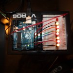
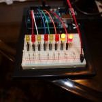
Pictures of Setup:
Diagram & Parts:
Needed:
1x Arduino Uno Board
1x Arduino Uno Prototyping Board
8x Short Wires
2x Long Wires
8x 330 ohm Resistors
8x LED lights (as many colors as you want)
Setup:
1 Long Wire from 5v to Positive on Prototyping Board + (right side)
1 Long Wire from GND to Negative on Prototyping Board – (right side)
1 Resistor from J7 to – (right side)
1 Resistor from J10 to – (right side)
1 Resistor from J13 to – (right side)
1 Resistor from J16 to – (right side)
1 Resistor from J19 to – (right side)
1 Resistor from J22 to – (right side)
1 Resistor from J25 to – (right side)
1 Resistor from J28 to – (right side)
1 LED with Positive G8 to Negative G7
1 LED with Positive G11 to Negative G10
1 LED with Positive G14 to Negative G13
1 LED with Positive G17 to Negative G16
1 LED with Positive G20 to Negative G19
1 LED with Positive G23 to Negative G22
1 LED with Positive G26 to Negative G25
1 LED with Positive G29 to Negative G28
1 Short Cable from Arduino Digital Pin D9 to F8
1 Short Cable from Arduino Digital Pin D8 to F11
1 Short Cable from Arduino Digital Pin D7 to F14
1 Short Cable from Arduino Digital Pin D6 to F17
1 Short Cable from Arduino Digital Pin D5 to F20
1 Short Cable from Arduino Digital Pin D4 to F23
1 Short Cable from Arduino Digital Pin D3 to F26
1 Short Cable from Arduino Digital Pin D2 to F29
Let me know if you encounter any problems!

