In the ongoing saga of getting our remote door buzzer system done, we have reached a major milestone: I’ve put the components on a prototype stackable board (as opposed to the quick prototype side board). This meant a lot of soldering and a lot of wiring to figure out. It was a very strange process, but Dan gave me a hand to me and we figured it out slowly but surely.
Here are some pictures to get you an idea of what I’m talking about:
-
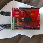
- In action
-
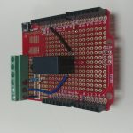
- Top view
-
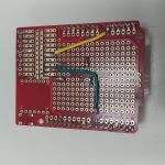
- Bottom view
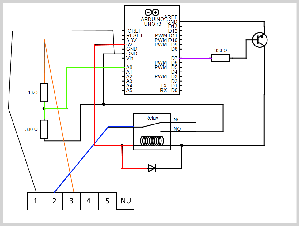
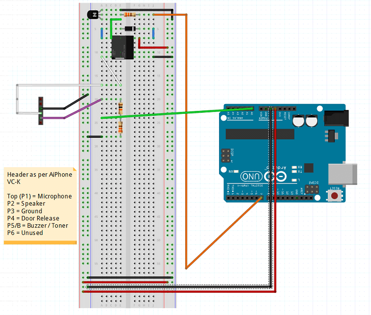
So that’s the long and short of it. You’ve got three wires coming into the header, from left to right they are: panel ground (required to make the door buzzer trigger, Arduino ground is not sufficient), door latch (the lead that connects to the door, when grounded opens the door), door buzzer (when someone presses the button at the door, 12v is applied to this line).
Now for the write up:
- Header Pin 1 (Ground) to Common Ground Rail
- Header Pin 2 (Door Latch) to 5V Relay Common Contact
- Header Pin 3 (Door Buzzer) to Voltage Divider consisting of: 1K Ohm resistor and 330 Ohm resistor.
- Voltage Divider to Arduino Analog Pin 0.
- NPN Transistor (P2N2222A) Collector to Diode Negative to 5V Relay Coil Negative
- NPN Transistor (P2N2222A) Emitter Common Ground Rail
- Arduino Digital Pin 7 to 330 Ohm Resistor to NPN Transistor (P2N2222A) Base
- Arduino Ground to 5V Relay Normally Open Contact
- Common 5V Rail to Diode Positive to 5V Relay Coil Positive
Explanations:
Header Pin 1 to Ground so that the common ground can be used for triggering the door latch. Header Pin 2 to 5V Relay Common Contact so that when the 5V Relay Coil gets energized the 5V Relay Normally Open Contact gets connected to Common Ground via Arduino Ground. Header Pin 3 has to get into a Voltage Divider because the Arduino does not like 12V entering it. This Voltage Divider will take 12V and downsample it to ~3V, which means we can have about 20V hit it before it makes the Arduino sad (max input voltage is 5V). We need the NPN Transistor to actually trigger the 5V relay because the Arduino pins don’t provide enough current to power the coil properly (much to my sadness). Since we’re using a Transistor to pump up the current flow, we also need a Diode to make sure we don’t burn out components. It’s basically being used to discharge extra current. All because the Arduino can’t trigger the relay itself. Sad.
I’m working on a circuit diagram but I’ve never drawn one out before so I hope you bear with me. I used a tool called Circuit Diagram to make the basic outline and then used Paint.net to color in the lines to try and make it clearer where wires go and what not… This is very difficult and strange for me. 😐
Here’s a picture from Fritzing which I think is better.
I’m currently working on a 3D printed case for the whole unit. Here’s a preview of that!
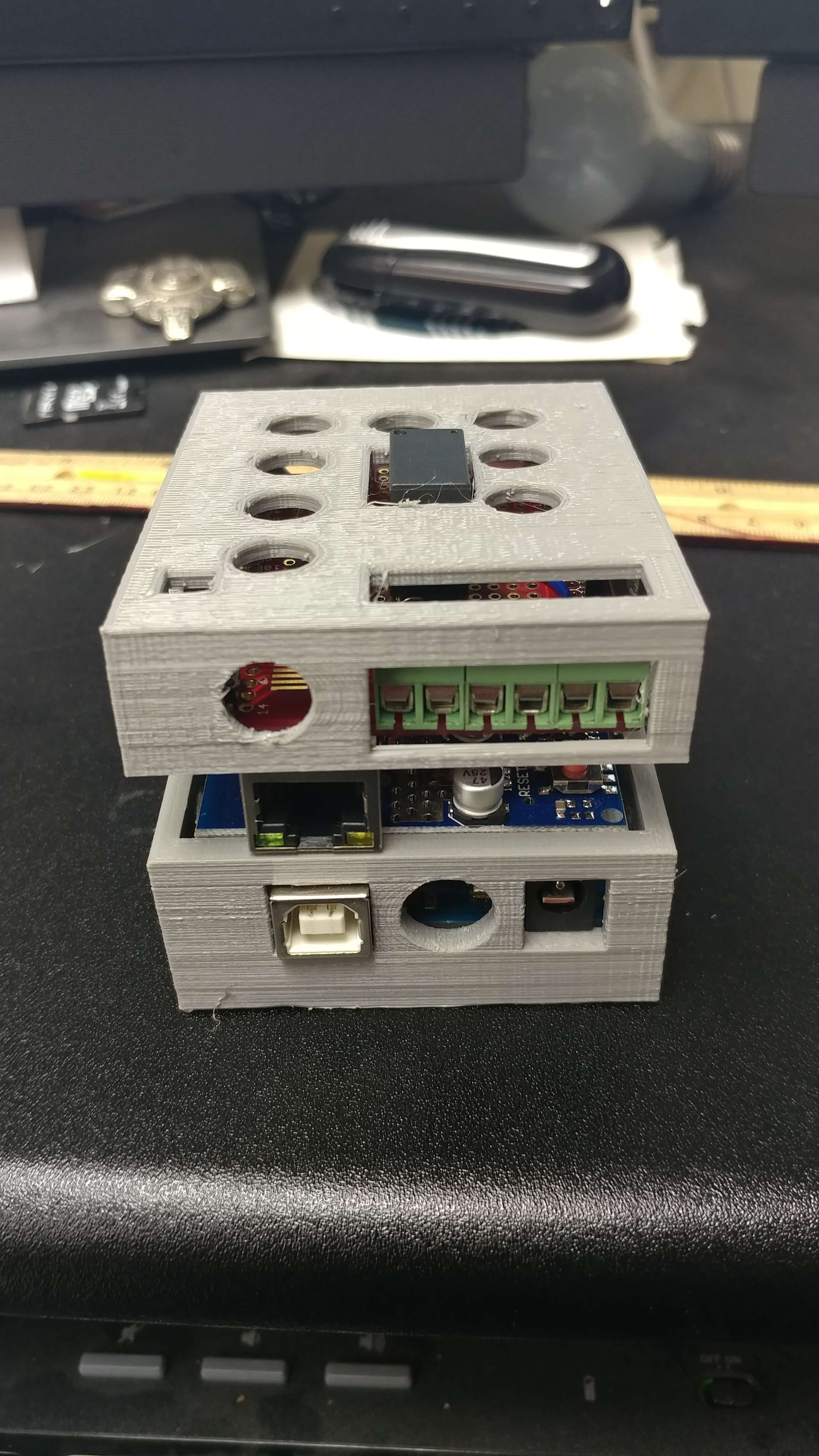
Just need to take the top template I have been provided (thanks Dan!) and modify it so that my top is there. 😀
Next step: marketing. >_> The end is near.
-M, Out.