So, first of all let me state for the record I had 3 Grande House Margaritas this evening, one of which was a Coronarita, and I may be a little incoherent at this point.
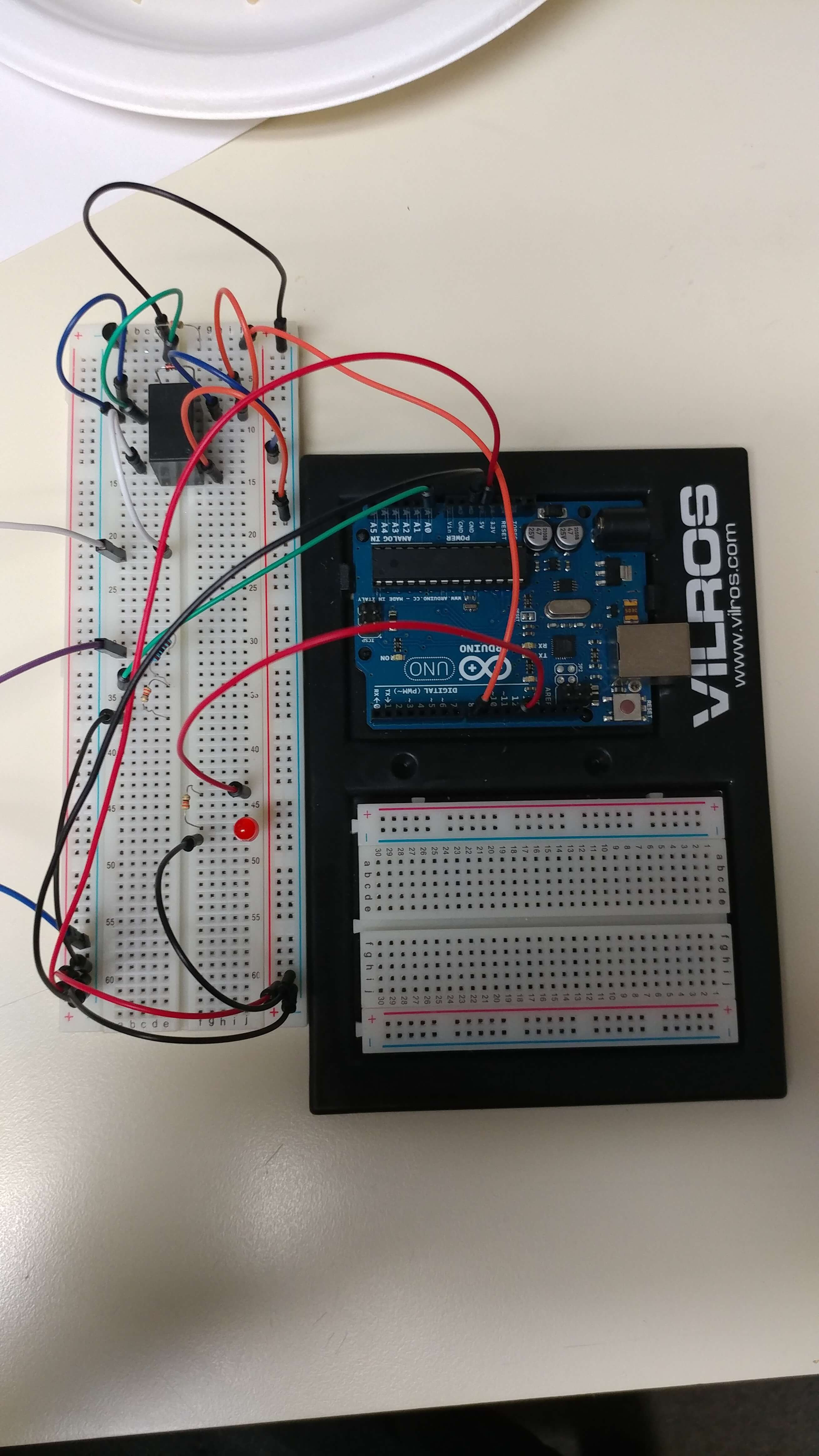
Down to business: we have a working prototype alpha of the Remote Building Entry Unlocker. It doesn’t do anything fancy. If you push the button at the door, it rings the buzzer, lights up the unit, and then unlocks the door. Woo!
It is a little more complex than one would expect, since the Arduino can’t sense above 5v, and the door panel is 12v. Also the Arduino native ports can’t really trigger a relay coil off anything not the 5v rail (though I suppose I could have just used a pin as ground with a toggle on that, but it’s neither here nor there).
Here’s the build and code.
Parts Needed:
- Arduino Uno
- Breadboard
- Assorted lengths of jumper wire
- 5v Relay
- Diode
- 3 330 Ohm resistors
- 1 1K Ohm resistor
- 1 LED
- 1 P2N2222A Transistor (NPN, BJT)
Wiring Guide:
- Arduino 5v to Breadboard +
- Arduino Ground to Breadboard –
- Breadboard – to Transistor Pin 3 (Emitter)
- Arduino Pin 8 to 330 Ohm Resistor 1 to Transistor Pin 2 (Base)
- Transistor Pin 1 (Collector) to Relay Coil side A
- Diode to Relay Coil side A (outside of Transistor Pin 1)
- Breadboard – to Relay Coil side B
- Diode to Relay Coil side B (outside of Breadboard -)
- Breadboard – to Relay Triggered Pin.
- Door Panel Latch Pin to Relay Common Pin
- Door Panel Buzzer Pin to 1K Ohm Resistor
- Arduino Pin A0 to 10K Ohm Resistor & 330 Ohm Resistor 2
- Breadboard – to 330 Ohm Resistor 2
- Arduino Pin 12 to 330 Ohm Resistor 3 to LED +
- LED – to Ground
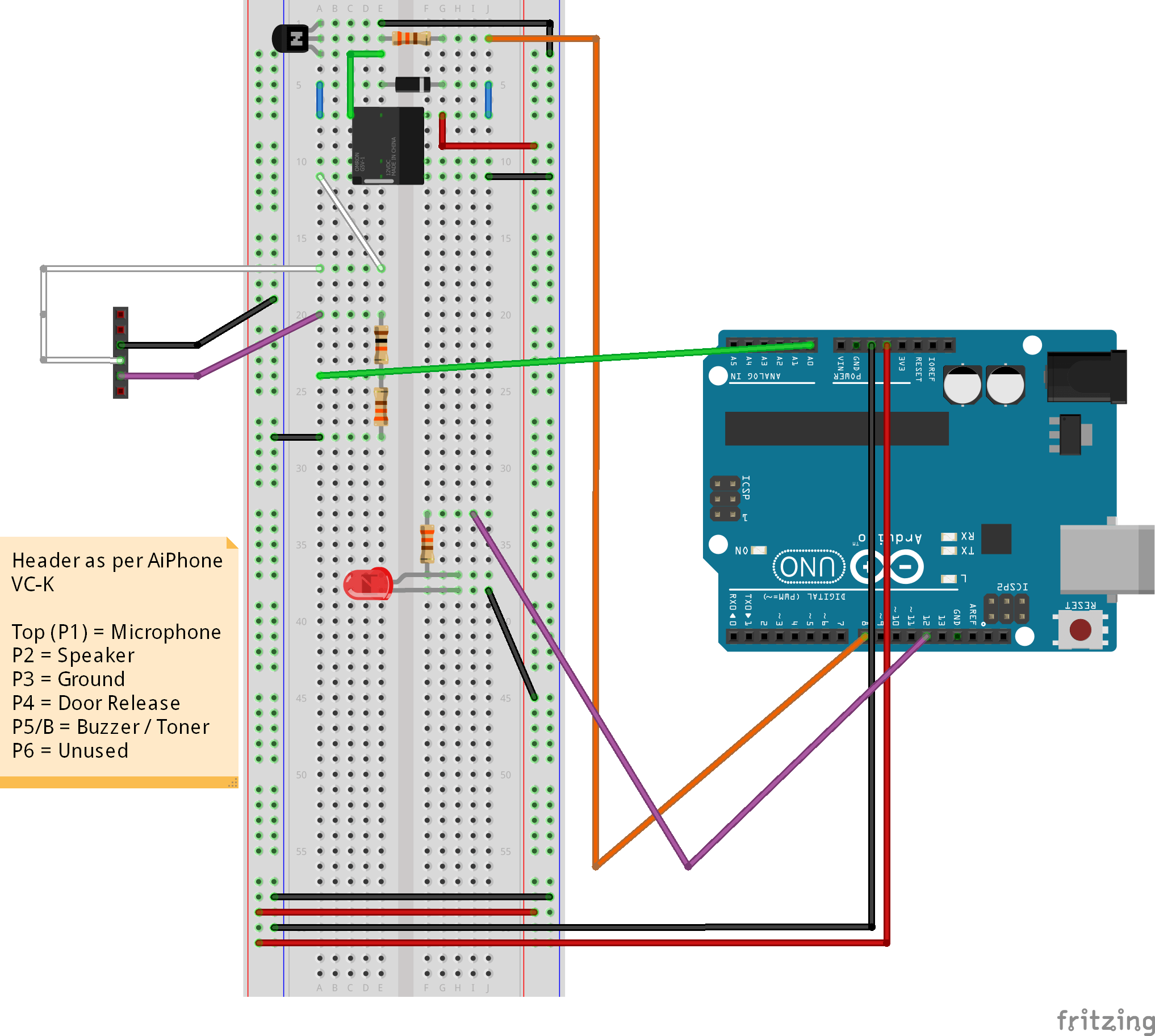
Fritzing Wiring Guide:
Code:
// Test Buzzer Implementation v1.0
// A0 reads input from buzzer
// If A0 > 7.5V, and last is < 7.5V, then trigger fires
// If A0 > 7.5V, and last is >= 7.5V, ignore
// If A0 < 7.5V, and last is >= 7.5V, end trigger
// If A0 < 7.5V, and last is < 7.5V, ignore

int buzzerPin = 0; // Pin A0 on Uno
int latchPin = 8; // Pin 8 on Uno
int ledPin = 12; // Pin 12 on Uno

float vOut = 0.0;
float vIn = 0.0;
float lastvIn = 0.0;
float threshhold = 7.5;

float R1 = 1000.0; // resistance of R1 (1000 Ohms)
float R2 = 330.0; // resistance of R2 (330 Ohms)
// This will ideally allow 20V to be downsampled to ~5V, allowing for overvoltage of the usually max 12V signal.
// This is an Arduino Voltage Divider, found here: http://www.electroschematics.com/9351/arduino-digital-voltmeter/

int value = 0;

void setup(){
    pinMode(buzzerPin, INPUT);
    pinMode(latchPin, OUTPUT);
    pinMode(ledPin, OUTPUT);
    digitalWrite(ledPin,LOW);
    Serial.begin(9600); // All Serial commands can be omitted as necessary, they were useful for debugging.
}
void loop(){
    value = analogRead(buzzerPin);
    vOut = (value * 5.0) / 1024.0;
    vIn = vOut / (R2/(R1+R2));
    Serial.print("Volage: ");
    Serial.println(vIn);
    if(vIn >= threshhold){
        Serial.println("Voltage Above Threshhold...");
        if(lastvIn < threshhold){
            Serial.println("Trigger!");
            digitalWrite(ledPin,HIGH);
            digitalWrite(latchPin,HIGH);
        }
        else{
            Serial.println("Ignore.");
            // We can ignore it, we have already been alerted
        }
    }
    else if(vIn < threshhold){
        Serial.println("Voltage Below Threshhold...");
        if(lastvIn > threshhold){
            Serial.println("Cancel Trigger");
            digitalWrite(ledPin,LOW);
            digitalWrite(latchPin,LOW);
        }
        else{
            Serial.println("Ignore.");
            // We can ignore it, trigger should have stopped already
        }
    }
    lastvIn = vIn;

    delay(2500); // Decrease it to a lower value or higher value, as you need.  It sets how long the buzzer needs to be pressed and
    // how long the door stays unlatched!
}
Description:
When outdoor button is pressed, buzzer is triggered with a 12V signal. The 12V enters a voltage divider with 1K Ohm and 330 Ohm resistors. This will drop the voltage to approximately 3V (this is to provide over-voltage protection). The Arduino code vIn = vOut / (R2/(R1+R2)); converts the received voltage back to the true voltage. If it’s above 7.5V, we can assume the buzzer has gone off (the buzzer idles at 2V). This triggers a pulse to the transistor which causes the relay to trigger. The relay grounds the Door Latch pin and causes the door to unlock. The diode serves to prevent too much current at our 5V relay.
And the best part is: it works. This means it’s trivial to add an Arduino Wifi Shield and make it do things across the network.
I am completely giddy. I would be able to send a packet from my Smartphone to my home network to trigger and unlock my door for a specified number of seconds.
That’s the next step.
Holy nuts.