So, if you’ve been following the saga of the Remote Door Buzzer System, you’re probably aware that we’ve finished making the template board and moved onto the case itself.
I wanted to provide an update as to the overall design.
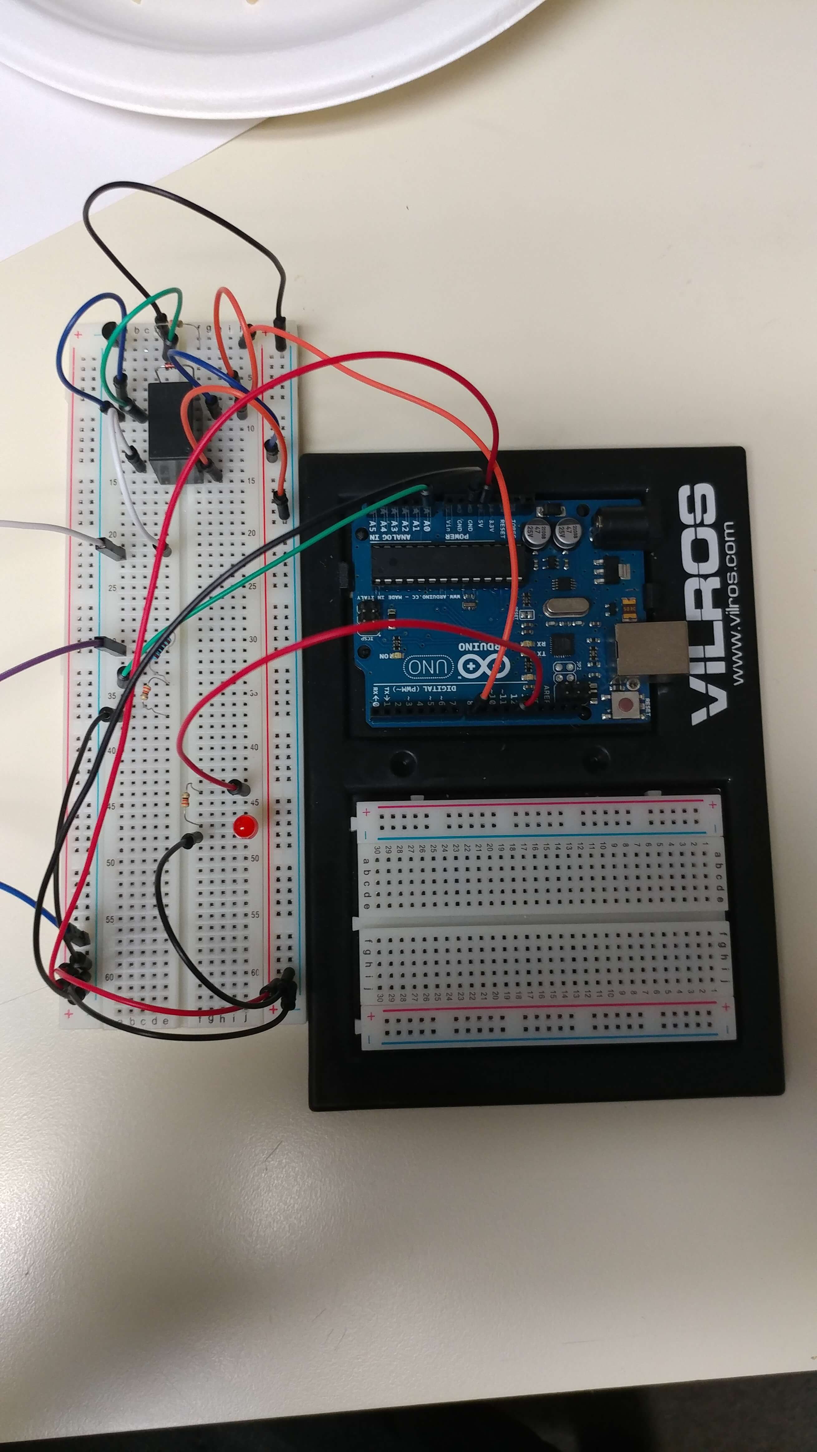
This is what we’re looking at so far:
-
- Prototyping the fit
-
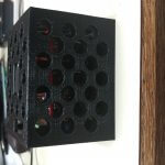
- A completed print
-
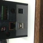
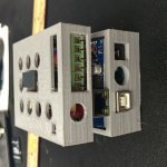
- Front view
-
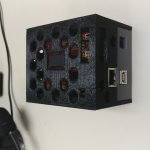
- Side view
You can see the original print had all 6 header pins available, we modified that so only the 5 pins that correspond to the 5 door buzzer system lines are visible. We’re probably going to drop the top layer down a bit to hide more of the pin header, but that’s trivial. The cut out for the relay and the cut out for the reset button are functional. The holes all line up (yay ventilation!). Everything looks good.
The next step is to seal the unit up (we’re debating using brass screw inserts like these to make the case connect together, but we’re unsure how it will work with the minimum fill that we use to keep the weight down) and run some raceway down the wall.
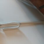
In fact, here’s what the completed install looks like:
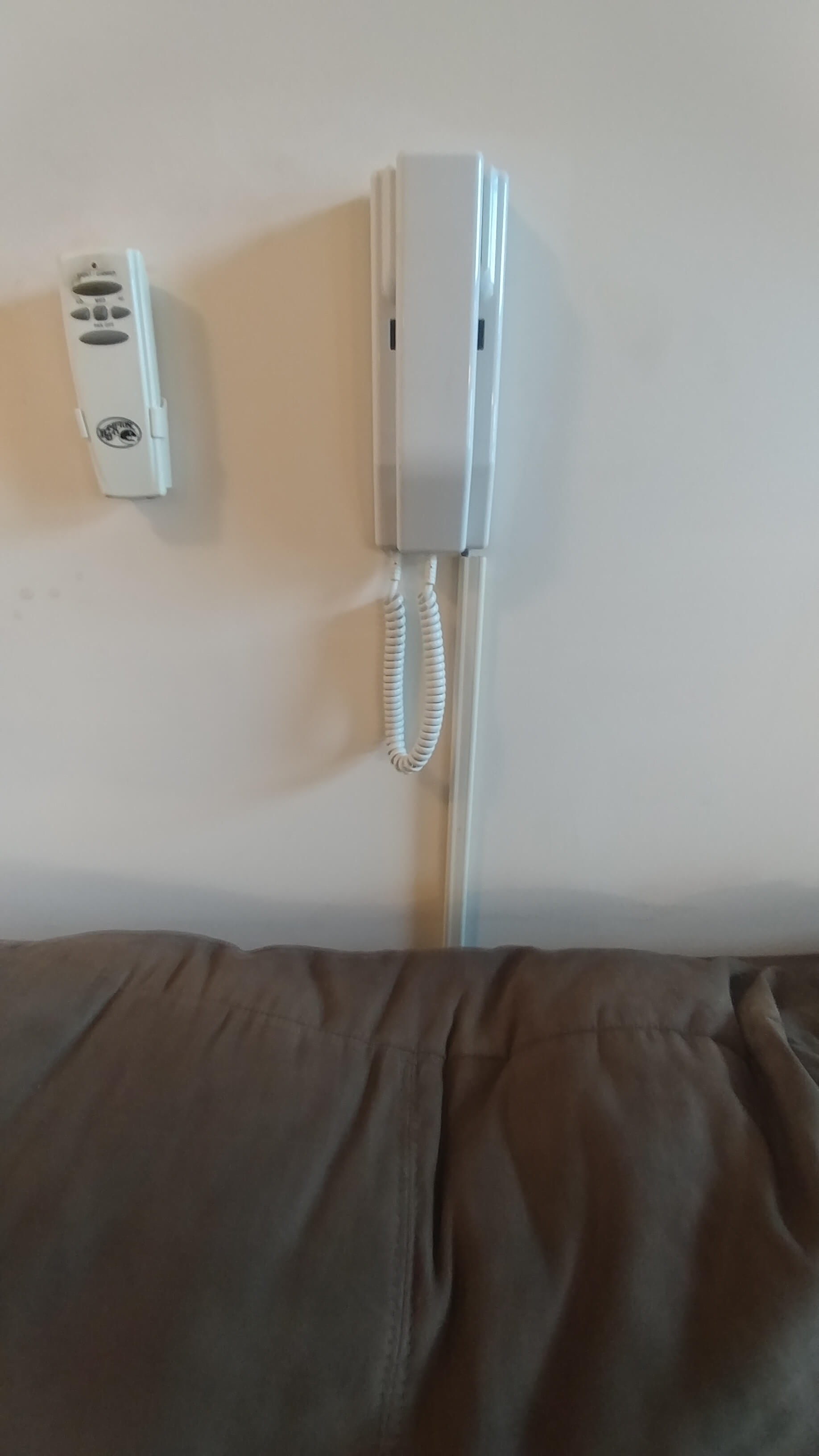
We used a piece of Cat5e cable to run the wires in the raceway.
-
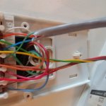
- Wiring in the wall plate.
-
- Look at that sexy raceway.
-
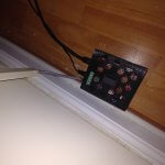
- Box now sits on the floor, under the couch. 😀
All in all, this project is pretty well done at this point, at least for now. It may be done for good since we may be getting forced to leave the apartment due to a… disagreement with the landlord.
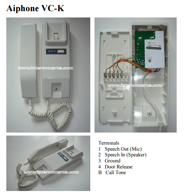
I still want to get the audio pins to do something, but there’s problems with interpreting raw audio signals on Arduinos, and there’s been a lot of discussion on it.
There are some guides here and here but I’ve read horror stories of fried Arduinos because the input sound signal is +/- 5v, and the -5v on an input pin can result in lots of bad news. I wanted to dive into that aspect of it immediately but it’s also summer and summer work is generally nuts so I won’t have time to work on the development of it for a while. Womp womp.
I may end up investing in an audio shield, but I don’t know how it’ll go because they mostly use 3.5mm jacks as input and all I need is a wire lead.
More research to follow.
-M, out.